描述
Good drawings save money twice: once when the panel is built and again every time somebody has to find a fault five years later.
Schematics
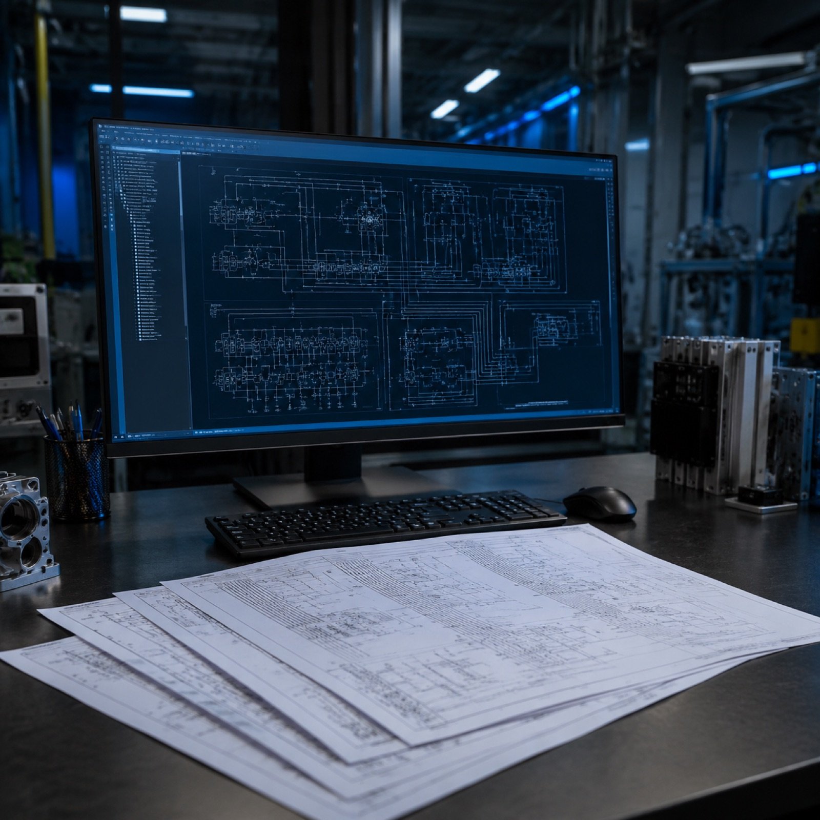
Drawn in EPLAN with a consistent page structure — supply and distribution, safety circuit, digital inputs and outputs, analogue signals, drives, network. Cross-references are generated rather than typed, so contacts and coils always point at each other correctly.
Wire numbering and device tags follow the numbering convention you already use in your plant. If there is no convention, we propose one and apply it consistently.
Control panel design
Component layout with real dimensions, duct fill checked rather than assumed, heat load calculated for the enclosure and the cooling sized to match. Terminal strips are grouped by function and by cable route, which is what makes wiring fast and fault-finding possible.
I/O lists and documentation
The I/O list is the document that links the electrical design to the PLC program, and it is the one most often left half-finished. Ours carries the tag, the description, the module and channel, the cable and the field device — and it stays in step with both the drawings and the program.
The delivered set includes schematics, panel layout, terminal and cable lists, parts list and the native EPLAN project so you are not dependent on us for the next revision.